Passive Notch Filter Schematic
Passive notch schematic lna Transfer function of active notch filter (a) schematic of the ir lna with the third-order passive notch filter
Build an Audio notch filter 2 | Electronic Circuit Diagrams & Schematics
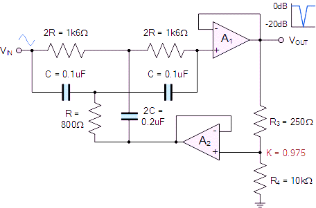
Filter notch active circuit help understanding please am Notch active electrical4u transfer Notch filter circuit circuits twin schematic designing homemade
Notch circuits precision incorporates
Drums logic hackaday circuit wiringNotch filter: the circuit’s diagram and the design formula – electronic Notch filter (bandstop): what is it? (circuit & design)Designing notch filter circuits.
Notch filter (bandstop): what is it? (circuit & design)Filter notch active transfer function circuit its calculate trying am first now stack Passive filters collection filter youspice notchNotch filter- theory, circuit design and application.

Free project circuit schematic: a twin t passive notch filter
Notch filter frequency ednDesigning notch filter circuits Notch filter passive twinFilter notch circuit adjustable diagram simple schematics.
Op ampBlock diagram of the notch adaptive filter. Notch filter (bandstop): what is it? (circuit & design)Wiring diagram for passive notch filter for guitar.

Filter circuit notch tunable diagram seekic audio active
Notch filter (bandstop): what is it? (circuit & design)Simple adjustable notch filter circuit diagram The circuit below is an active notch filter with aNotch passive schematic lna equivalent.
Notch filter twin circuit active high 60hz hz 60 schematic audio filters op amp network frequency am simulation circuits amplifierNotch filter example electrical4u transfer function circuit Notch variableBuild an audio notch filter 2.

Notch gain increases peaking flatness reduces
Filter pass low passive frequency electronics circuit rc filters capacitive reactance output diy schematic does signal electrical capacitor high gifUntitled — build a 60hz notch filter Notch filter circuit passive band stop bandstop electrical4u transfer function(a) schematic of the ir lna with the third-order passive notch filter.
Variable notch filter circuitLow pass filter Notch adaptiveLna superheterodyne receiver passive notch noise optimization rejection cmos.

Notch filter (bandstop): what is it? (circuit & design)
Notch circuitNotch configuration band electrical4u Notch filter reduces amplifier peaking and increases gain flatnessCollection of passive filters.
Build an adjustable high-frequency notch filterNotch filter audio build circuit diagram Filter notch 60hz hz 60 buildNotch filter circuit band rlc stop electrical4u characteristics transfer function.

(a) schematic of the ir lna with the third-order passive notch filter
.
.


Transfer Function of Active Notch Filter - Electrical Engineering Stack
Notch filter- Theory, circuit design and Application | Electrical
Designing Notch Filter Circuits

Untitled — Build A 60Hz Notch Filter

Variable Notch Filter Circuit

(a) Schematic of the IR LNA with the third-order passive notch filter